Arduino prototyping with a breadboard
A breadboard is a reusable construction base for prototyping electronics. It has a number of rows of spring-equipped holes, the holes of each row galvanically connected to each other. The holes are spaced at the standard 0.1" grid, allowing many standard electronics packages to be directly pushed to the breadboard. The breadboard may not be electronically suitable for high speed or sensitive measuring, but it is a very rapid prototyping method used within its limits.

Figure 1. A typical breadboard, with the leads visible
A typical breadboard is made of a plastic shell that holds together conductive, spring-equipped plates. These plates are arranged on a DIL package friendly pattern, in a 0.1 inch grid. The leg of a electronic component or a wire is simply pushed to a hole to make a contact. All the legs and wires on a row are connected together. In the case you are still confused (as Pekka was back in October 2012), there are more depth articles on how to use a breadboard. If you are using a breadboard for the first time, it is very easy to make false assumptions about the connectivity of the holes in a breadboard. The multimeter is your friend; do check connectivity if you are in doubt.
The pattern of a breadboard is usually formed around a cleft at the middle. Perpendicular to the cleft are rows of holes. In a typical case, a DIL-packaged chip is inserted straddling the cleft, with each leg of the DIL connected to its own terminal strip, i.e. a row of holes. All holes on the same row on the same side of the cleft are connected to each other. On bigger breadboards, there are usually a number of buses; however, the Arduino shield breadboards typically have no busses at all.
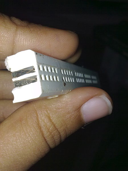
Figure 2. The internal structure of a breadboard (from WikiMedia)
In this workshop, we have prepared a number of Arduino Shields that have some soldered sensors and a small piece of breadboard for building the buck converter. Our small breadboard has only the terminal strip blocks (rows of holes) and no buses.

Figure 3. A typical Arduino shield breadboard
Contrary to what a beginner may assume, the terminal strip blocks (rows of hole) are not connected to any Arduino pins. The Arduino pins are only connected to the Arduino headers.
As modern electronics go, the electric part of a design usually is spread to several small submodules each connected to a central micro controller. Simple schematics are prime grounds for applying the breadboard as a development tool.
To convert a schematics into a breadboard configuration, one should first consider each network, or a wire connecting component legs, in the schematics. Each such wire must be mapped into a terminal strip on the breadboard. In some cases, a wire must be mapped into several terminal blocks, e.g. because there are more legs connected to a wire than a single terminal block can hold, or because the component physical dimensions simply cannot be fit into a single-block design. In such a case, the terminal strips must be interconnected with a separate wire.
It may be beneficial to design and document a breadboard configuration on a graph paper. However, if you have little or no experience in using a breadboard, just starting to plug in the components and moving them around may be the easiest way to start, as you will learn by practise how the components fit in. Of course, extensively moving the components have the drawbacks that the breadboard springs become gradually looser and it is quite easy to break or twist component legs when inserting them to the breadboard. But don't worry, we do have some extra components.
It is usually easiest to start with the components with strictest legs, such as ICs in a DIL package, or FETs or other active components in a big package, e.g. TO-220 package. It may be best to place these relatively central to the breadboard. One can then move outwards from these components, designing each wire network separately. The ground and power wires (so called rails ) are typically but not necessarily placed outmost.
Initially, when trying a design, component legs are usually not cut and components may hang in a haphazard-looking arrangement with an army of wires engtangling the whole mess. This is completely normal in the initial phases. Try to bend the components so as not to touch each other. If possible, leave some space around each component so that an oscilloscope probe can be fit most anywhere.
When you are satisfied that a module works, it is possible to replace the long bendy wires with cut-to-length solid wires and cut all component legs to a desired length. This will make a breadboard prototype last a transit and tolerate handling much better. However, if you're running out of time and it works, don't touch a working circuit. Prettyfying a module may introduce mistakes and you will be set back.